Proximity Operations of Formation Flying Spacecraft
- Jan 8, 2018
- Article
-
 Astrogator
The formation flying concept is becoming really important these days, especially since the development of nano, micro, or small satellites capable of carrying Earth Observation payloads. The usage of this kind of satellite instead of a single, massive satellite improves flexibility and reliability, and greatly reduces cost.
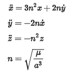
If the leader follows a circular Keplerian orbit, then the natural relative motion of the chaser(s) flying close to the leader can be described by the following set of linear differential equations, known as the Hill-Clohessy-Wiltshire equations:

Where,
x is in the in-track directiony is in the radial direction
z is in the out of plane direction
It is interesting to note that the relative motion has a sinusoidal component along the out of plane direction, which is decoupled from the in-plane motion that follows a closed ellipse when there is no in-track drifting.
The following discusses how to propagate and display the relative motion calculated in STK, starting from an initial condition defined accordingly with the HCW equation set.
Step 1 – Configure and run Astrogator
Astrogator easily simulates the relative motion using the Differential Corrector search profile, which automatically computes the various relative initial states of the chaser resulting in prescribed formation geometries. A screenshot of the Differential Corrector configured for this problem is shown below.
The Cartesian state of the chaser satellite is systematically changed until the intended results (relative motion parameters) are matched. When the differential corrector converges, the initial state is propagated ahead in time from the Astrogator’s propagator.
Step 2 – Configure the Graphics
By default, the satellite orbits are shown with respect to the inertial reference system. Users can change this setting by going to Satellite Properties -> 3D Graphics -> Orbit System and selecting the VVLH (the orbit reference) system with respect to the reference satellite. By doing this, the pattern followed by the chaser is shown with respect to the reference satellite, which is stationary in the relative reference system.
Below are two screenshots. On the top, we have a constant, ellipsoidal pattern that has been generated starting with an in-track and cross—track offset and radial rate only. On the bottom, the same initial state has been used, plus a small rate in the in-track direction. This generates an in-track drift and the chaser satellite now follows an elliptical cylinder.
Step 3 – Define Maneuvers
In case we need to evaluate the effects of station keeping or collision avoidance maneuvers during formation flying, STK offers the ability to apply custom strategies in the Mission Sequence. The image below shows the effect of two maneuvers performed by the chaser satellite in order to change the relative geometry between satellites. The maneuver time has been automatically calculated using the eccentricity/inclination vector separation strategy, as explained in the paper Proximity Operations of Formation-Flying Spacecraft Using an Eccentricity/Inclination Vector Separation written by Simone D’Amico and Oliver Montenbruck.
Specific strategies can be implemented using Analysis Workbench, which allows the definition of vectors, angles, planes, and reference frames through which the user can define custom stopping conditions for the Mission Sequence.
Finally, Astrogator automatically calculates the amount of fuel needed to perform each maneuver, allowing the estimation of the overall fuel budget for the entire mission.
To see a demonstration of the Flying Formation concept in STK, play the following narrated video:

