Preparing CAD models for STK with Ansys Discovery 2022 R1
- Mar 18, 2022
- Blog Post
-
 Systems Tool Kit (STK)
Install
The STK 12.4 install disc includes a new utility that helps convert CAD models to use in STK. Look for it in a folder called “Discovery_STK_ModelAddIn” (or “SpaceClaim_STK_ModelAddIn” if you’ve not yet made the leap from Ansys SpaceClaim to Ansys Discovery). You may also download it from the web. Once the utility is installed, the main ribbon across the top of Discovery should sport a new tab called “Systems Tool Kit (STK)."

When you see this tab, you’re ready to create and convert models for STK! The first step is to import the existing model, if there is one. Discovery has built-in importers for many popular formats including STEP, IGES, AutoCAD, SolidWorks, and others. Discovery is also a CAD authoring environment, meaning you can create your own models from scratch here, or make edits and refinements to any model that you’ve imported.
Keep It Simple
STK needs only a subset of the engineering details a CAD model has to offer. A tangle of internal geometry hidden from view will only slow down your scenario. Think about whether you need to see all 572 rivets in full splendor, or if those represent excess detail that could be trimmed for speed. If the latter, Discovery offers built-in tools for bulk-selecting and simplifying or removing those details. The “Power Select” feature earns its name here.

Export to STK
The leftmost button on the STK tab will export the model to a *.glb file, which is the binary form of the Khronos glTF 2.0 format. This format is different from traditional CAD model formats. It’s intended as a display-ready format, storing the data in a similar manner to what a graphics chip needs as raw input. STK can load the model directly from the Object Properties, 3D Graphics Model tab.
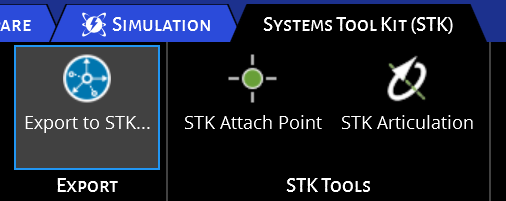
Add an Attach Point
Transmitters, receivers, cameras, and sensors all need a location on the model. Mark any such locations on your model as a Discovery “Point” (an actual Datum Point, not a sketch point).

By default, a new point will be called “Point.” Expand the document tree on the left and rename the point to something that will be recognizable in STK and is not the same as any other point name in the document.
Then, visit the STK tab and activate the “STK Attach Point” tool by clicking on it. Once active, the tool will ask you to select a point and choose whether that point is an STK Attach Point.

In this example, a point has been renamed to “DishAttachPoint,” and the STK Attach Point Tool is active. The user has selected the point and used the HUD to enable it as an STK Attach Point.
After adding one or more Attach Points and marking them for use in STK, click “Export to STK…” again to save an updated version of the glTF model file, and reload it in STK. Beware that Discovery has its own “Save As…” menu with a glTF format option, but this is a different exporter that does not include STK-specific extensions such as Attach Points and Articulations. When creating a model for STK, always use the “Export to STK…” function, either from the ribbon bar or from its own menu entry. You should also save the Discovery project the normal way, so it will retain these settings for your next session.

With the newly updated model loaded into STK, you can now use the Attach Point, for example, by assigning a Vertex Offset to a sensor.
Add Some Articulations
Moving parts make a visualization come alive. The STK Articulation Tool marks parts as being able to translate, rotate, and/or scale in STK.

Any part of the model that can move independently from the rest of the model must be placed in its own “component.” Discovery offers a context menu option called “Move to New Component” that can migrate parts into separate components so that they can articulate separately. The name of the component will be the name of the articulation in STK. The STK Articulation Tool asks you to select an individual component and then toggle the available transformations.
Rotation is a type of transformation where the order is significant. This tool names the rotations Yaw, Pitch, and Roll, and you can control the ordering with a drop-down box. The drop-down offers choices for which axis (X, Y, or Z) corresponds to Yaw (making it the first rotation), which axis is Pitch (the second), and Roll (the third). The text field below each one enables model-specific names to replace the Yaw, Pitch, Roll nomenclature (for example, a spinning wheel might have a transformation named “Drive” instead of “Pitch”).
Model Pointing
In the case of a steerable part such as the antenna dish pictured above, the “Roll” axis can be exchanged for a “pointing” axis instead. When pointing is used, no move or scale transformations should be enabled on that component, and exactly one or exactly two rotations should be enabled. In the example above, the dish can “Yaw” (change its compass heading) by rotating about the Y axis (the green vector). It can “Pitch” by rotating about the Z axis (the blue vector), but it is constrained to +90 degrees (the positive rotation is always counterclockwise when looking directly at the tip of the vector as shown). The business end of this dish is aligned with +X (the red vector), so that is the pointing vector. A part can never rotate about its own pointing vector, since that does not change the direction it points to. The drop-down box for this part reads “Yaw Y, Pitch Z, Pointing +X,” and Yaw and Pitch are both enabled.
Once exported to STK, model pointing can be enabled under the STK object properties, 3D Graphics, “Model Pointing” tab.
Axis and Origin
Most independent parts have a particular axis or location that should be the center of rotation or scale. When there is a single, non-pointable axis of rotation and / or translation, use an “axis” for simplicity, otherwise use a full “origin.” Both are available from the “Design” ribbon:

Once added to the model, this can act as the central axis or central origin for a component’s articulation. The axis or origin object must itself be a direct child member of the component that needs it. The orientation is significant and does not need to be axis-aligned to the design’s root origin. The “Move” tool can move and arbitrarily rotate an axis object or an origin object.
Next, the new axis or origin object must be selected as the basis of the articulation for a component. You can do this by clicking the “Choose Axis or Origin” button in the margin of the STK Articulation Tool’s HUD, followed by a click on the desired axis or origin.

Above, the middle arrow indicates the “Choose” button, and the side arrows show that “DishOrigin” has been chosen as the origin for this component’s articulations. When the drop-down box display begins with “Yaw Y,” it means the green +Y vector on the DishOrigin object, because of this choice.
Once these settings are applied, remember to save your work and then use “Export to STK…” to export a new model for your scenario.
Check out the STK 12.4 page to learn more.
Happy model building!
Author
Systems Tool Kit (STK)
Modeling and simulation software for digital mission engineering and systems analysis.