Generate a Transformation Matrix in Analysis Workbench
- Feb 12, 2018
- Tech Tip
-
 Analysis Workbench
In today’s blog, I’m going to show you how you can use the Vector Geometry Tool (VGT) in Analysis Workbench (AWB) to generate a transformation matrix between any two reference frames that your heart desires! The basic approach is to create unit vectors for a dummy object in one frame, and then express each of those vectors in your second frame. You can then compose the transformation matrix from those three vectors.
For this example, assume that I want the transformation matrix between the Mars Inertial Frame and J2000 at the J2000 epoch. Here's the procedure, step by step:
- Create a new scenario and set the scenario start time to be the J2000 epoch (1 Jan 2000 11:58:55.816 UTCG ). Set the stop time to be +1 hr. Add in a dummy satellite (you can keep all of the default satellite values).
- Right-click on your satellite in the Object Browser and select Analysis Workbench.Click on the 'Create new Vector' button.
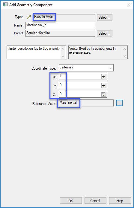
- Select 'Fixed in Axes' for Type – this means that the vector is fixed by its components in a reference frame – in our case, that’s Mars Inertial. Name this vector something like “MarsInertial_X”. Use Cartesian coordinates, and simply create a unit vector by specifying X = 1, Y = 0, Z = 0. For Reference Axes, choose 'Mars Inertial' (you’ll have to filter by ‘All STK Objects’ on the left).
- Repeat Step 3 to create similar vectors for “MarsInertial_Y” (X = 0, Y = 1, Z = 0) and “MarsInertial_Z” (X = 0, Y = 0, Z = 1). Now you have a set of unit vectors expressed in the Mars Inertial frame.
- Next, right-click on the satellite in the Object Brower and select Report & Graph Manager... Click the 'Create New Report Style' button ( ). Call the new report something like “Mars Inertial X in J2000”. In the Data Providers column, expand Vectors(J2000), and then expand the MarsInertial_X folder (corresponding to the unit vector we just created). Bring 'Time', 'x', 'y', and 'z' over to the right. Give x, y, and z more significant digits by highlighting each one, clicking Options…, and increasing the Number of Decimal Digits.
- Click OK and then generate the report. The first line represents our unit vector expressed in the J2000 frame, at the J2000 epoch.
- Repeat Steps 5 and 6 for Mars Inertial Y in J2000 and Mars Inertial Z in J2000.
- Now you have all of the information you need to compose your transformation matrix! The first row in each report (corresponding to the J2000 epoch) is simply the corresponding column in the matrix. For example, this report...
...gives you the following matrix:
So there you have it! Just another example of how STK and AWB can be used to quickly and easily solve your vector geometry problems.
Author

Analysis Workbench
Create custom functions and calculations relative to times, positions, and reference frames.