New Feature in STK 11.1.1 - New Lighting Constraint
- Mar 20, 2017
- Tech Tip
- Multidomain
-
 STK Pro
Sometimes… right when you think you’ve got this world figured out, something so unbelievable happens. Something bewildering. Like dogs and cats living together… mass hysteria! What I’m talking about here folks, is the AGI development team sneaking a NEW FEATURE into an 11.1.x maintenance release of STK! Seriously? This is a thing they do now? I feel so strange! Honestly, in these moments, I find it best to just take a breath, move forward, and talk about it… so let’s get to it.
New in STK 11.1.1 (I know…) is a lighting constraint called the LOS Sun Illumination Angle. In other technical disciplines, you might hear of this angle referred to as the illumination phase angle or even the Camera-Target-Sun (CATS) angle. Whichever you call it, it is the angle measured at the target object location between the vectors pointing to the Sun and the observer. I drew a picture: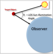 LOS Sun Illumination Angle
If you’re unfamiliar with this measurement, a LOS Sun Illumination angle (phase) of 0 degrees indicates that the full face of the target (as seen from the observer) is illuminated. Think illumination phases of the moon as seen from earth. 0 degrees equals a full moon, 180 degrees equals a new moon.
Why would you want to use this constraint in STK? Great question… Imagine you’re working a program for a constellation of satellites in low-earth orbit (LEO) which observe objects in the geosynchronous (GEO) orbital regime. Also imagine that you know your optical payloads can only detect objects up to a certain visual magnitude. At this point, as a good engineer, you’ve probably also determined that for targets of given size and reflectivity, the Sun Illumination Angle has the most effect on a target’s apparent visual magnitude at LEO to GEO observation distances. Maybe you’ve built a table like the one below…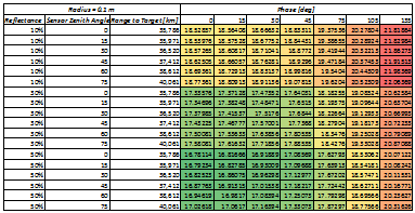 Example Table
Knowing these angles, and using them as constraints in STK, will allow you to observe when your constellation’s optical payloads meet the conditions to achieve the visual magnitude for detection. This information could also be used to build an optimal sensor pointing schedule for multiple targets.
To access this constraint, go to an object’s Properties>Constraints>Sun constraints. There you are able to set a minimum and maximum LOS Sun Illumination Angle. The documentation for the Sun/Lighting constraints can be found in STK’s documentation.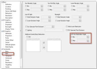 Location of Sun/Lighting in STK
The images below are of a scenario where a single GEO satellite has a payload that is tasked to dwell on the Target_Sat at GEO. Using Analysis Workbench, I generated a custom angle between the LOS Access vector between the two satellites and Target_Sat’s Sun Vector. I then enabled those vectors and the angle in Target_Sat’s 3D Graphics properties.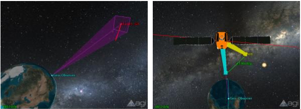
This timeline view shows the periods of access GEO_Observer’s sensor has with Target_Sat without applying a LOS Sun Illumination angle constraint. Notice the consistent periodicity to the accesses due to GEO_Observer’s orbital period.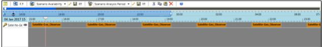 Consistent period of access
When I apply an arbitrary Sun Illumination constraint of 35-75 degrees, notice how the accesses are immediately affected over the identical time-span. Not only do several accesses not meet the criteria altogether, the accesses that remain during this timeframe are shorter (width of the orange access bars) due to the application of the constraint.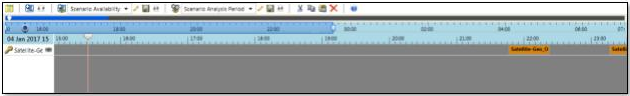 Constraint applied
As a point of clarification, this constraint is not the same as the LOS Solar Exclusion Angle which has been a feature in STK for some time (and likely added in a normal development cycle… not a maintenance release!). The LOS Solar (or Lunar) exclusion angle allows you to ignore access to another object if it is within a user-specified number of degrees from the sun (or moon). This constraint allows you to model conditions where your sensor payload might need to shield itself as the sun passes through it’s field of view… to keep from melting components or some other terrible consequence. A visual of that constraint is below.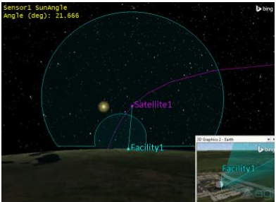 Lighting Constraint in 3D
New in STK 11.1.1 (I know…) is a lighting constraint called the LOS Sun Illumination Angle. In other technical disciplines, you might hear of this angle referred to as the illumination phase angle or even the Camera-Target-Sun (CATS) angle. Whichever you call it, it is the angle measured at the target object location between the vectors pointing to the Sun and the observer. I drew a picture:
LOS Sun Illumination AngleIf you’re unfamiliar with this measurement, a LOS Sun Illumination angle (phase) of 0 degrees indicates that the full face of the target (as seen from the observer) is illuminated. Think illumination phases of the moon as seen from earth. 0 degrees equals a full moon, 180 degrees equals a new moon.
Why would you want to use this constraint in STK? Great question… Imagine you’re working a program for a constellation of satellites in low-earth orbit (LEO) which observe objects in the geosynchronous (GEO) orbital regime. Also imagine that you know your optical payloads can only detect objects up to a certain visual magnitude. At this point, as a good engineer, you’ve probably also determined that for targets of given size and reflectivity, the Sun Illumination Angle has the most effect on a target’s apparent visual magnitude at LEO to GEO observation distances. Maybe you’ve built a table like the one below…
Example TableKnowing these angles, and using them as constraints in STK, will allow you to observe when your constellation’s optical payloads meet the conditions to achieve the visual magnitude for detection. This information could also be used to build an optimal sensor pointing schedule for multiple targets.
To access this constraint, go to an object’s Properties>Constraints>Sun constraints. There you are able to set a minimum and maximum LOS Sun Illumination Angle. The documentation for the Sun/Lighting constraints can be found in STK’s documentation.
Location of Sun/Lighting in STKThe images below are of a scenario where a single GEO satellite has a payload that is tasked to dwell on the Target_Sat at GEO. Using Analysis Workbench, I generated a custom angle between the LOS Access vector between the two satellites and Target_Sat’s Sun Vector. I then enabled those vectors and the angle in Target_Sat’s 3D Graphics properties.
Vectors in 3D Graphics window
This timeline view shows the periods of access GEO_Observer’s sensor has with Target_Sat without applying a LOS Sun Illumination angle constraint. Notice the consistent periodicity to the accesses due to GEO_Observer’s orbital period.
Consistent period of accessWhen I apply an arbitrary Sun Illumination constraint of 35-75 degrees, notice how the accesses are immediately affected over the identical time-span. Not only do several accesses not meet the criteria altogether, the accesses that remain during this timeframe are shorter (width of the orange access bars) due to the application of the constraint.
Constraint appliedAs a point of clarification, this constraint is not the same as the LOS Solar Exclusion Angle which has been a feature in STK for some time (and likely added in a normal development cycle… not a maintenance release!). The LOS Solar (or Lunar) exclusion angle allows you to ignore access to another object if it is within a user-specified number of degrees from the sun (or moon). This constraint allows you to model conditions where your sensor payload might need to shield itself as the sun passes through it’s field of view… to keep from melting components or some other terrible consequence. A visual of that constraint is below.
Lighting Constraint in 3DAuthor
STK Pro
The foundation for analyzing and visualizing complex systems in the context of their missions.
Analysis Workbench
Create custom functions and calculations relative to times, positions, and reference frames.
Systems Tool Kit (STK)
Modeling and simulation software for digital mission engineering and systems analysis.